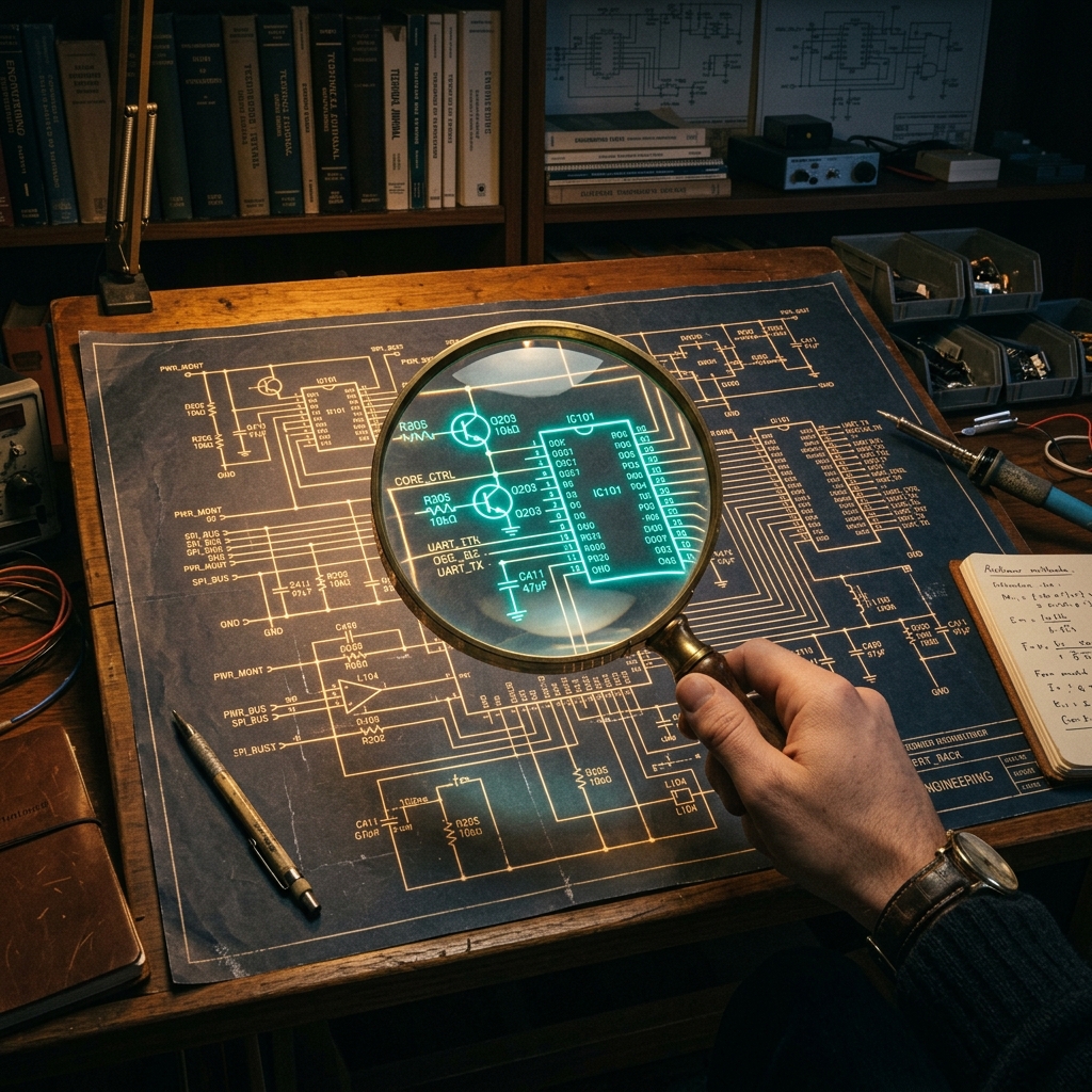
beginners Circuit Diagram Maker Team

How to Read a Circuit Diagram: A Step-by-Step Guide

Learn how to read a circuit diagram step by step. This beginner-friendly guide explains symbols, power flow, labels, wires, and how to understand simple schematics with confidence.

beginnerstutorialeducationschematic-reading

Interactive Article Panel

Diagram + table companion

Switch between reading, building, and review views for a quick technical summary of this article.

How to Read a Circuit Diagram: A Step-by-Step Guide

Reading flow

How to inspect a schematic logically

Start with supply rails, trace the active path, then verify labels and outputs so the circuit becomes easier to understand block by block.

POWER find rails first SIGNAL trace the path LOAD confirm output

Interactive reference table

Updates live
Step 1 Identify power and ground
Step 2 Follow the signal path
Step 3 Read values and labels
Step 4 Split the circuit into blocks

How to Read a Circuit Diagram: A Step-by-Step Guide

If you are new to electronics, one of the most useful skills you can learn is how to read a circuit diagram. A good schematic tells you what components are used, how they connect, where power enters the circuit, and how a signal moves from input to output.

At first, circuit diagrams may look abstract or intimidating. But once you understand the symbols and reading order, they become much easier to follow. This guide breaks the process down into a simple step-by-step method for beginners.

What Is a Circuit Diagram?

A circuit diagram, also called a schematic diagram, is a symbolic drawing of an electronic circuit. Instead of showing physical appearance, it shows the logical electrical connections between parts.

For example:

  • A resistor is shown with a standard resistor symbol
  • A capacitor is shown with two plates
  • A battery is shown as a power symbol
  • Wires are drawn as simple lines

The goal is clarity. A circuit diagram does not try to show what the finished hardware looks like on a board. It shows how electricity is meant to move through the system.

Why Learning to Read Circuit Diagrams Matters

If you can read a schematic, you can:

  • Understand how a circuit works
  • Troubleshoot faults more effectively
  • Follow electronics tutorials with confidence
  • Build projects more safely
  • Communicate designs with other students, engineers, or hobbyists

Whether you are studying a simple LED circuit or a more advanced microcontroller design, the same reading method still applies.

The Main Parts of a Circuit Diagram

Before going step by step, it helps to know the main elements you will see in almost every schematic.

Components

These are the symbols that represent electronic parts such as resistors, capacitors, diodes, transistors, and ICs.

Wires

Wires are shown as lines connecting symbols together. They represent electrical connections, not physical cable routing.

Junctions

When wires connect, there is usually a dot at the junction. If two wires cross without a dot, they are usually not connected.

Labels

Schematics use labels like:

  • R1, R2 for resistors
  • C1, C2 for capacitors
  • U1 for integrated circuits
  • VCC, 5V, GND for power rails

These labels make the circuit easier to describe and debug.

Step 1: Learn the Most Common Symbols

The first step in reading a circuit diagram is to recognize the basic symbols.

Symbol TypeComponentWhat It Usually Does
Resistor symbolResistorLimits current or divides voltage
Capacitor symbolCapacitorStores charge, filters noise, couples signals
Diode symbolDiodeAllows current in one direction
LED symbolLEDEmits light when current flows
Ground symbolGroundReference point for voltage return
Battery or supply symbolPower sourceFeeds the circuit
IC symbolIntegrated circuitPerforms logic, control, amplification, or processing
Transistor symbolBJT or MOSFETSwitches or amplifies signals

If you are still learning symbols, our component library and Circuit Diagram Symbols Explained guide are good next resources.

Step 2: Find the Power Source and Ground

When you start reading any schematic, identify the power rails first.

Look for labels such as:

  • VCC
  • 3.3V
  • 5V
  • 12V
  • GND

This tells you where the circuit gets power and where current returns.

Why This Step Matters

Once you know the supply and ground, the rest of the diagram becomes easier to interpret. You can begin tracing how the power reaches each component block.

Step 3: Follow the Signal Path

Many schematics are organized so the signal moves:

  • Left to right
  • Sometimes top to bottom

This is not a hard rule, but it is a common convention.

When reading the circuit:

  1. Find the input
  2. Follow the wires through each stage
  3. Identify what happens in the middle
  4. Find the final output or load

This approach is much easier than trying to understand the whole circuit at once.

Step 4: Read the Component Labels and Values

A symbol alone tells you the part type, but the label tells you which specific part it is in the design.

Examples:

  • R1 means the first resistor
  • C3 means the third capacitor
  • U1 means the first IC
  • Q2 means the second transistor

The value text tells you the actual electrical value:

Label ExampleMeaning
10k10 kilo-ohms
220Ω220 ohms
100µF100 microfarads
1N4148Specific diode part number
LM358Specific op-amp IC

These values are essential for understanding how the circuit behaves.

Step 5: Break the Circuit into Functional Blocks

One of the best ways to understand a schematic is to divide it into sections.

For example, a circuit might contain:

  • A power supply block
  • A sensor input block
  • A processing or logic block
  • An output block

Instead of reading every wire individually right away, first ask:

What is each block supposed to do?

Then look more closely at the components inside each section.

Example: How to Read a Simple LED Circuit Diagram

A simple LED circuit is a great first example.

Typical Parts

  • Battery
  • Resistor
  • LED
  • Ground or return connection

Reading Order

  1. Start at the battery positive terminal
  2. Follow the wire to the resistor
  3. Follow the next connection to the LED
  4. Follow the return path back to the battery negative or ground

What the Circuit Does

The resistor limits current so the LED does not burn out. The LED then lights when current flows in the correct direction.

This simple example already teaches several core ideas:

  • Power source
  • Current path
  • Series connection
  • Polarized component

Example: How to Read a More Complex Schematic

Now consider a circuit with:

  • Sensor input
  • Op-amp
  • Microcontroller
  • Output LED or transistor

You can read it in layers:

Input Stage

Look at what signal enters the circuit first. This may be from a sensor, switch, or connector.

Conditioning Stage

An op-amp or filter may adjust the signal before it goes to the controller.

Processing Stage

A microcontroller or logic IC reads the signal and makes a decision.

Output Stage

The output may drive an LED, buzzer, relay, or MOSFET.

Once you look at it this way, even a larger schematic becomes more manageable.

Common Mistakes Beginners Make

Confusing Crossing Wires with Connected Wires

Always check for a junction dot. Crossing lines alone do not always mean a connection.

Ignoring Component Polarity

LEDs, diodes, electrolytic capacitors, and many IC power pins must be connected in the correct direction.

Skipping Labels

Reference designators and values provide critical information. Do not ignore them.

Trying to Understand Everything at Once

Focus on one path or one functional block at a time.

Tips to Read Circuit Diagrams Faster

  • Start with familiar symbols first
  • Identify the power rails before anything else
  • Read the circuit one section at a time
  • Use labels and values to understand purpose
  • Redraw a simple circuit yourself to reinforce the logic

If you want hands-on practice, the easiest method is to rebuild a simple schematic visually inside an editor.

Practice Method for Beginners

One effective learning technique is:

  1. Open a simple schematic
  2. Identify power, ground, and the main signal path
  3. List each component and its value
  4. Recreate the same circuit in a clean editor

This forces you to read the diagram actively rather than passively.

You can practice that workflow directly in the Circuit Diagram Maker editor.

Final Thoughts

Learning how to read a circuit diagram is less about memorizing everything at once and more about following a repeatable process. Start with the power rails, identify the symbols, trace the signal path, and break the circuit into logical blocks.

With regular practice, schematic reading becomes much faster and more intuitive. To keep learning, explore our Circuit Diagrams for Beginners, The Ultimate Guide to Circuit Diagrams, How to Make a Circuit Diagram Online, and documentation. If you want to practice immediately, open the editor and recreate a simple LED or op-amp circuit yourself.